
Dam Seepage Control: 7 Ways to Stop Seepage in Dams
Reviewed September 2026 against USGS Water Resources Investigations, USDA Economic Research Service, and U.S. Army Corps of Engineers case-study data.
Try it: Run your own numbers →
Dam seepage control means installing one or more of seven engineered barriers — cutoff walls, grouting, drainage galleries, relief wells, impervious blankets, geosynthetic liners, or slurry walls — sized to the dam’s foundation geology and monitored with piezometers and seepage meters. Seepage in dams is not automatically a failure sign: some seepage is expected in every embankment dam, and the engineering question is whether the rate is stable, decreasing, or accelerating. Left unmanaged, dam seepage was implicated in roughly 28% of constructed-dam failures in historical USGS data, via a mechanism called piping — the progressive internal erosion of fine soil particles until a tunnel-like void forms and the structure loses support.
This guide covers where seepage originates, the seven engineered countermeasures used to control it, what each one costs, and how to read the instrumentation data before a minor leak becomes a structural event. It draws on U.S. Geological Survey (USGS), USDA, and U.S. Army Corps of Engineers case files rather than generic engineering summaries, because the queries this page answers — dam seepage, seepage in dam, and dam seepage control — are searched by people who need numbers, not definitions.
Contents
Understanding Dam Seepage: Sources & Pathways
Seepage in a dam follows three distinct pathway categories, and identifying which one is active determines which of the seven controls below actually applies. Engineers separate them because a fix for one pathway does nothing for another — a drainage blanket installed for foundation seepage will not stop seepage moving through the dam body itself.
Key Sources of Seepage in Dam Structures
- Through the dam body: internal cracks, construction joints, interfacial gaps between compacted lifts, or inherently porous fill material.
- Through the foundation and abutments: pathways along rock fractures, permeable soil seams, or washed-out layers beneath the dam. These can move the largest volumes fastest if uncharacterized during design.
- Along the interface where the dam meets natural terrain: preferential flow at the abutment contact, the downstream toe, or around outlet conduits where compaction against a structure is hardest to achieve.
How Seepage Pathways Form
- 🔗 Material defects — in-situ soil heterogeneity or construction flaws introducing cracks and voids in the embankment.
- 💧 Fractured rock foundations — jointed, weathered, or fissured rock strata channeling seepage below the impervious core.
- 🌱 Abutment contact seepage — flow developing along the interface between the dam and the natural valley wall.
- 📉 Downstream erosion channels — subsurface flow surfacing at the toe, which is the visible warning sign of piping in progress.
Why Dam Seepage Control Is Essential
Dam seepage control matters for two separate reasons that get conflated in most explanations: structural safety and water-supply economics. On the safety side, USGS’s historical review of constructed-dam failures attributes roughly 28% of them to piping and seepage-related mechanisms — making it one of the largest single failure categories, alongside overtopping (USGS Water Resources Investigations Report 87-4250). On the economic side, uncontrolled seepage is a direct water loss that shows up on an irrigation district’s books every season, independent of whether the dam is structurally at risk.
Left unmanaged, seepage in dams can:
- ⚠ Cause piping — progressive removal of fine soils creating internal tunnels that lead to sudden failure, often with little external warning until late stages.
- ⚠ Waste stored water — reducing the reservoir’s usable yield for the irrigation season or industrial process it was built to serve.
- ⚠ Move contaminants — carrying tailings chemistry or agricultural runoff into groundwater or downstream surface water.
- ⚠ Undermine foundations — loss of bearing strength at the toe or abutments, which can trigger slope instability.
- ⚠ Accelerate surface erosion — concentrated exit flow at outlets degrading the downstream face over successive wet seasons.
Treating minor seepage on small or medium earthfill dams as cosmetic. USGS’s failure-cause data puts piping and seepage among the leading causes of embankment dam failure historically — the scale of the dam does not exempt it from the mechanism.

How Much Water Does Seepage Actually Cost?
Before choosing a control method, it helps to know the baseline loss you are fighting. USGS field measurements of unlined irrigation canals found seepage losses of 32% to 41% of inflow — meaning nearly a third to two-fifths of the water released never reaches the field it was meant for (USGS Water Resources Investigations Report 87-4250). Canals lined with earth or native soil — a step up from bare-earth ditches but still a passive lining — lose 20% to 50% of conveyed water, per Colorado State University Extension’s review of USDA irrigation data (Colorado State University Extension).
The upside is that lining works: permanent canal liners — compacted clay, concrete, or geomembrane — cut seepage losses by up to 97% compared to unlined sections, according to USDA Economic Research Service irrigation organization data (USDA Economic Research Service). That 97% figure is a ceiling for well-installed, well-maintained lining — not an average across all lined canals, since lining quality and age both degrade the number in practice.
Real system-level data backs this up at scale. USGS gauged the Fox ditch irrigation system’s annual seepage loss at 2,100 acre-feet in 2012 and 2,200 acre-feet in 2013 — enough water, at roughly one acre-foot per acre-year of typical irrigated crop demand, to have irrigated over 2,000 additional acres each of those seasons had it been captured (USGS Scientific Investigations Report 2014-5091). At the reservoir scale, USGS measured 18,500 acre-feet of seepage and aquifer recharge beneath Sand Hollow Reservoir in Utah during the 2017–2018 water year — illustrating that even a modern, engineered reservoir can lose a five-figure acre-foot volume to seepage in a single year, some of which is deliberate aquifer recharge and some of which is uncontrolled loss (USGS Open-File Report 2022-1089).
These figures are historical measurements at specific sites and years, not a national annual total — no consolidated USDA statistic exists for total U.S. irrigation water lost to seepage across all infrastructure. To size the loss for a specific canal or reservoir, use the USGS Water Data portal (waterdata.usgs.gov) to find seepage-run studies for the nearest gauged conveyance, since these are typically refreshed on the water-year cycle rather than continuously.
Assessment & Design: Laying the Foundation for Effective Seepage Control
Every dam seepage control program begins with site characterization, not method selection. Choosing a cutoff wall before confirming the depth and continuity of the permeable foundation layer is a common and expensive mistake — the wall can end up terminating above the layer it was meant to intercept. The core assessment steps are:
- ✔ Hydrology & hydrogeology: mapping water movement, recharge zones, and the pressure gradient driving seepage.
- ✔ Geotechnical evaluation: testing the structural properties of soil and rock in the foundation and abutments.
- ✔ Seepage pathway analysis: locating likely flow routes — defects, cracks, faults — through boring logs and geophysical survey.
- ✔ Critical zone identification: prioritizing the toe, abutments, and any previously repaired sections for instrumentation.
- ✔ Environmental impact review: confirming the chosen control method will not itself degrade downstream water quality during installation.
The U.S. Bureau of Reclamation’s Design Standards No. 13, Chapter 8 sets the national engineering reference for seepage analysis and control design on federal dams, and is the document a design engineer should be working from directly rather than a summary of it (U.S. Bureau of Reclamation Design Standards No. 13, Chapter 8). These standards are revised on a multi-year cycle as case history and materials science advance, so confirm you are reading the current edition before finalizing a design.
Thorough site characterization reduces downstream change-order risk. The Taylorsville Dam case below shows what happens to a budget when foundation conditions are discovered mid-project rather than during design.

Comparative Table: 7 Dam Seepage Control Methods
| Method | How It Works | Effectiveness (Seepage Reduction) | Relative Cost | Suitable Dam Types | Monitoring Requirement |
|---|---|---|---|---|---|
| Impervious cores & cutoff walls | Low-permeability barrier (clay, concrete, slurry) driven through the foundation beneath the dam body | 80%+ reported reduction; site-specific | High — Taylorsville Dam cutoff wall reached $24 million in final contract value | Large/medium earthfill, rockfill | Ongoing integrity checks via piezometers and geophysical survey |
| Zonal reinforcement & drainage galleries | Internal tunnels/chambers collecting and diverting seepage before it exits uncontrolled | High, but not separately quantified in available USGS/USBR data | Medium | Large embankment, tailings | Continuous flow-meter and turbidity monitoring |
| Downstream cutoff & toe drains | Perforated pipe or gravel trench along the downstream toe intercepting seepage before the slope | Not separately quantified; standard practice per USBR Design Standards No. 13 | Medium | Earthfill dams, tailings structures | Routine visual and flow inspection |
| Seepage relief wells & outlets | Perforated pipes/siphons relieving pore pressure buildup at controlled discharge points | Not separately quantified; relieves pressure rather than sealing pathway | Medium | Medium to large dams with confined aquifer layers | Outflow rate and turbidity tracking |
| Grouting & grouted anchors | Cementitious or chemical grout injected into foundation fractures and voids | Effective for sealing discrete voids; site-specific, no single published rate | Medium to high | Rockfill, fractured rock, older dams | Periodic verification via piezometers and borehole cameras |
| Surface erosion protection | Riprap, vegetation, or erosion control mats at seepage exit points | Reduces surface/piping risk rather than seepage volume | Low | Small to medium agricultural and forestry dams | Seasonal visual inspection |
| Plastic concrete cutoff wall | Flexible, low-permeability cutoff wall material used where ground movement is expected | High; Back Creek Dam (Maryland) installation is the documented cost benchmark below | $45 per square foot installed (1990, Back Creek Dam) | Dams on compressible or seismically active foundations | Ongoing integrity checks |
Two methods in this table carry a documented unit cost because they were the subject of published U.S. Army Corps of Engineers and Bureau of Reclamation case studies (cited in full in the case-studies section below); the rest do not have a single published effectiveness percentage in the source material reviewed for this article; treat the “not separately quantified” cells as an honest gap, not an omission — request a site-specific engineering estimate for these methods rather than relying on generic percentages you may see quoted elsewhere without a source.
Combine multiple seepage control measures rather than relying on one — for example, a cutoff wall paired with downstream drainage and relief wells addresses three different pathway types simultaneously.

7 Ways to Stop Seepage in Dams
Each of the seven methods below addresses a different seepage pathway or failure mode. Most functioning seepage control programs combine two or three of them rather than relying on a single fix.
1. Impervious Cores and Cutoff Walls
Impervious cores and cutoff walls are the primary barrier in most modern earthfill and rockfill dam designs: compacted clay, concrete diaphragm walls, or grouted cutoffs that run the width of the dam and tie into the foundation below the core.
- Installation: constructed beneath the dam to intercept seepage pathways through cracks or permeable rock before they can travel further downstream.
- Track record: soil-bentonite cutoff walls have been used since at least 1952, when the first such installation went into McNary Dam’s Kennewick Levee on the Columbia River in Washington State — a technique still in active use today (U.S. Bureau of Reclamation case study compilation).
- Monitoring: periodic integrity checks using geophysical tools and piezometric data, since a cutoff wall’s failure mode is often invisible until seepage resumes downstream.
Cutoff walls are especially valuable where foundation fractures or alluvial deposits run deep, and are widely applied to isolate mining tailings basins from surrounding groundwater.

2. Zonal Reinforcement and Drainage Galleries
Zonal reinforcement builds drainage blankets, internal wells, permeable filters, and drainage galleries into the dam’s body or abutments. These features:
- ✔ Collect seepage that penetrates the core zone or foundation cracks before it can accumulate pressure.
- ✔ Divert flow to controlled outlets or discharge points, reducing destructive pore pressure buildup.
- ✔ Stabilize the structure by preventing internal erosion and piping from initiating in the first place.
A well-designed drainage system lowers uplift pressure and maintains downstream stability — it is the difference between seepage exiting through a controlled channel versus finding its own uncontrolled path through the embankment.

3. Downstream Cutoff and Toe Drains
This is the last line of defense at the dam toe, intercepting seepage before it can exit through the downstream slope or abutments uncontrolled.
- ✔ Toe drains: perforated pipes or gravel-filled trenches along the downstream base that catch and discharge seepage in a controlled way.
- ✔ Drainage blankets: layers of free-draining granular material along the downstream toe, particularly effective for fine-grained soils that are susceptible to piping.
These systems matter most for agricultural earthfill dams and mining tailings structures, where downstream integrity and environmental protection carry both safety and regulatory weight.

4. Seepage Relief Wells and Controlled Outlets
Relief wells, controlled outlets, and siphons manage pore pressure buildup and give water an orderly path to exit without destabilizing the dam.
- ✔ Design: perforated or slotted pipes, sumps, and siphon tubes placed at points identified during the site characterization phase.
- ✔ Monitoring: outflow rate and turbidity are tracked to detect sudden changes indicative of piping or other developing failure.
- ✔ Benefit: relieves high-pressure zones, reducing the risk of a sudden blowout at the downstream face.
Relief systems matter most on medium to large dams where confined aquifer layers or artesian pressure heads threaten stability from beneath the structure.

5. Grouting and Grouted Anchors
Injecting cementitious or chemical grout into foundation fractures, abutment voids, or old construction joints increases resistance to seepage at the specific points where it is applied.
- Types: pressure grouting, curtain grouting, and jet grouting, each matched to the fracture geometry and environmental sensitivity of the site.
- Effect: fills voids and bonds loose material to seal discrete flow paths — it is a targeted repair, not a continuous barrier like a cutoff wall.
- Use cases: remedying leaks in rockfill, fractured rock, or older dams where a full cutoff wall retrofit would be disproportionate to the problem.
Grouted anchors additionally improve resistance to uplift and stabilize compromised foundation settings alongside their sealing function.

6. Surface Erosion Protection
Seepage exiting at the surface can cause erosion, gully formation, and slope failure if the exit point itself is not stabilized. Protection strategies include:
- ✔ Riprap or stone pitching: an armor layer that dissipates outlet velocity and stabilizes the surface it protects.
- ✔ Vegetation establishment: deep-rooted grasses and shrubs reinforce soils and slow surface flow rates.
- ✔ Erosion control mats: geotextiles that support rapid establishment of vegetation on newly exposed slopes.
This matters most for agricultural and forestry dams that see pulse discharges or seasonal overflow, where the exit point changes with the water level rather than staying fixed.
7. Instrumentation and Monitoring
Instrumentation is what turns seepage control from a one-time construction project into an ongoing management program. Standard instruments include:
- ✔ Piezometers: measure subsurface pore pressure in real time at fixed monitoring points.
- ✔ Inclinometers: detect subtle deformation, slumping, or settlement before it is visible at the surface.
- ✔ Turbidity sensors: track suspended fines in seepage discharge — a rising trend is the clearest available signal of internal erosion in progress.
- ✔ Seepage meters: quantify discharge rate directly, down to flows as low as 0.01 liters per second per meter of dam length.
Data from these instruments should be reviewed on a fixed schedule against pre-set threshold values — not just glanced at after a storm — so that a slow upward trend in turbidity or flow triggers a scheduled maintenance response well before it becomes an emergency.
- 🌟 Minimized seepage rates: less water lost from the reservoir’s usable supply.
- 🛡️ Enhanced dam stability: lower risk of catastrophic failure or downstream erosion.
- 🌱 Environmental protection: reduced contaminant transport and better-maintained downstream water quality.
- 💲 Cost-effective operations: proactive control avoids the multi-million-dollar remediation costs shown in the case studies below.
- 📡 Smart monitoring: data-driven maintenance scheduling rather than reactive emergency response.
mining.farmonaut.com
Accelerate mineral prospectivity mapping, foundation assessment, and remote seepage-risk analysis using satellite-based detection, without ground disturbance.
Canal Lining & Seepage Loss Calculator
The seepage-loss ranges above translate directly into an annual water-loss estimate for any specific canal once you know its flow rate and lining status — use the calculator below with your own numbers.
Run your own numbers
Assumptions: uses the loss-rate ranges from USGS Water Resources Investigations Report 87-4250 and USDA ERS irrigation organization reports; “permanent lined” applies a 97% reduction to the unlined midpoint rather than an independent loss figure, since no separate permanent-lining loss percentage was published in the source data. Excludes evaporation, operational spill, and seepage variation from soil type, water table depth, or lining age and condition — a site-specific USGS seepage run is the only way to measure your actual loss.
Real Seepage Control Projects and What They Cost
Published case files give the clearest picture of what seepage remediation actually costs once a problem is confirmed, rather than budgeted for at design stage.
Taylorsville Dam, Ohio: a self-hardening slurry cutoff wall project was initially estimated at $2.6 million with a 180-day construction timeline. By completion, the contract's final value had grown to $24 million — a roughly ninefold increase from the initial estimate, illustrating how foundation conditions discovered during construction can multiply seepage remediation costs well beyond the design-stage figure (U.S. Bureau of Reclamation case study compilation).
Back Creek Dam, Maryland: a plastic concrete seepage control wall was installed in 1990 by the U.S. Army Corps of Engineers at a unit cost of $45 per square foot — a useful benchmark for scaling a cutoff wall estimate by wall area, though material and labor costs have moved since 1990 and should be re-quoted against current pricing before budgeting a new project.
The gap between these two figures is the single strongest argument in this entire article for investing in site characterization before construction rather than during it: a $2.6 million estimate that becomes a $24 million contract represents cost growth almost entirely attributable to foundation conditions that were not fully characterized up front. For current per-square-foot or per-linear-foot pricing on a specific project, USDA-NRCS's Cost Share database and state irrigation district annual reports are the recommended sources, since material and labor costs shift annually and neither of the case studies above should be treated as a current quote.
Operational Aspects: Maintenance, Inspection & Emergency Response
Long-term stability depends on a systematic maintenance and response routine, not a single installation event. Best practices include:
- ✔ Routine inspections: check for fresh damp patches, surficial erosion, unusual vegetation growth, or turbidity in the outflow.
- 📊 Pore pressure tracking: use piezometer readings to flag problem zones before they progress to visible seepage.
- ⚠ Emergency protocols: lower reservoir levels, isolate failed outlets, and deploy temporary grouting or filter placement if piping is suspected.
- 🔍 Maintenance scheduling: clean drainage outlets, repair surface armor, and test monitoring equipment on a fixed calendar rather than reactively.
- 📝 Incident documentation: record every anomaly and intervention for regulatory compliance and design improvement over the dam's service life.
Skipping maintenance on downstream filters or ignoring small cracks. Both are exactly the kind of minor issue that the Taylorsville Dam case above shows can escalate into an eight-figure remediation if left unaddressed.
Environmental Considerations & Integrated Water Quality
Seepage control on agricultural, forestry, and mining sites intersects directly with environmental compliance:
- ✔ Contaminant containment: preventing tailings chemistry or agrochemical runoff from reaching groundwater or downstream surface water.
- ✔ Filtration barriers: outlet structures that trap sediment, heavy metals, and nutrients before discharge.
- ✔ Ecological considerations: choosing erosion-control and bioengineering techniques that reinforce habitat rather than degrade it.
- ✔ Water chemistry monitoring: tracking temperature, pH, and salinity at seepage outlets for early signs of contamination.
None of this is a "set and forget" program — thresholds for pore pressure, discharge rate, and turbidity should be reviewed and, where the data supports it, tightened as more seasons of monitoring data accumulate.
Satellite-Based Seepage Risk Mapping for Mining Sites
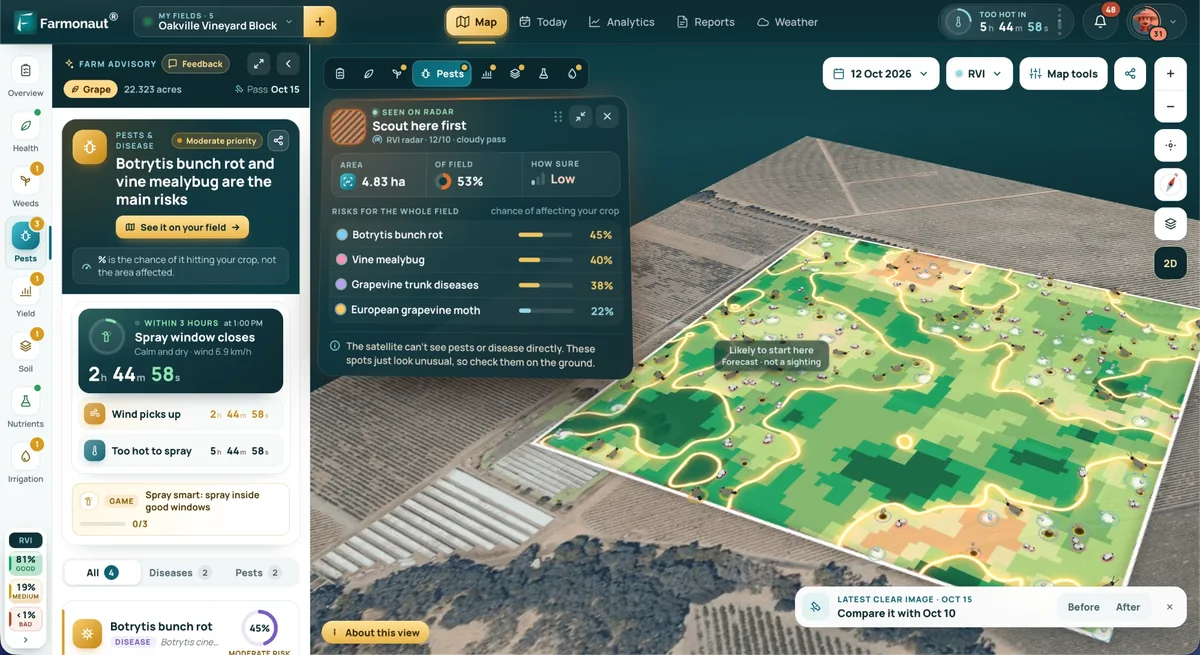
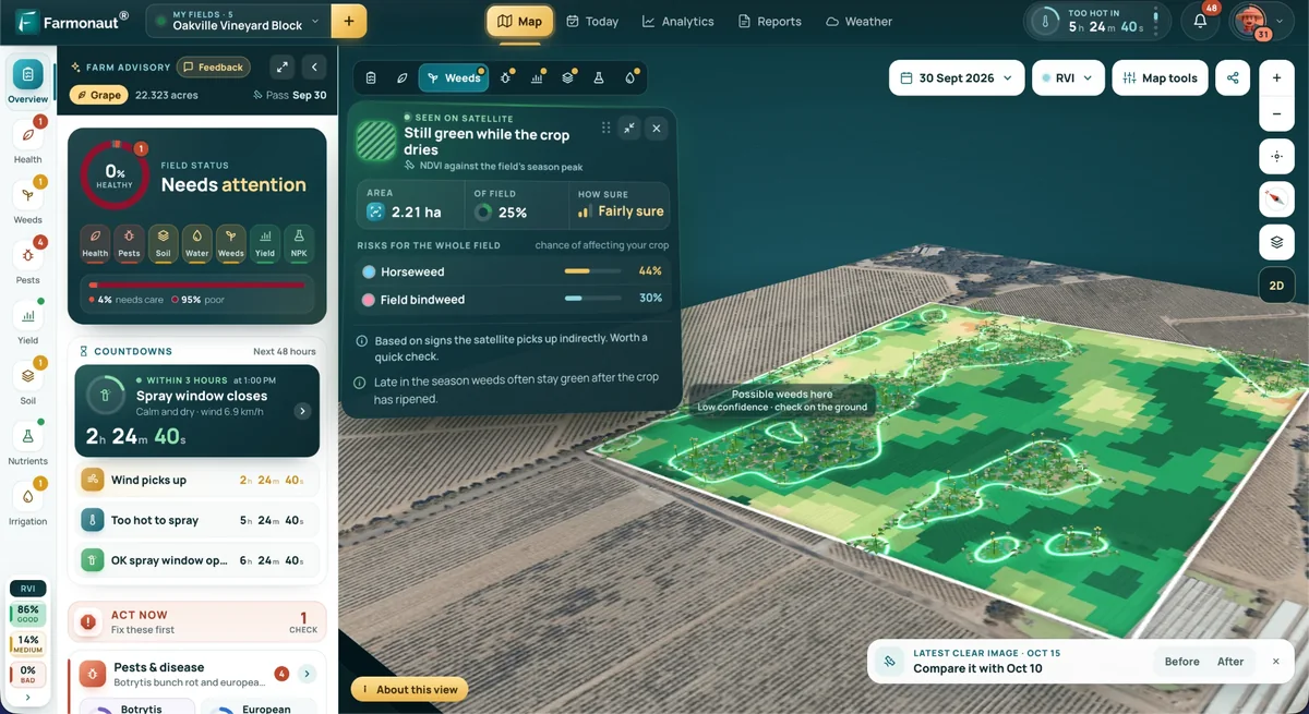
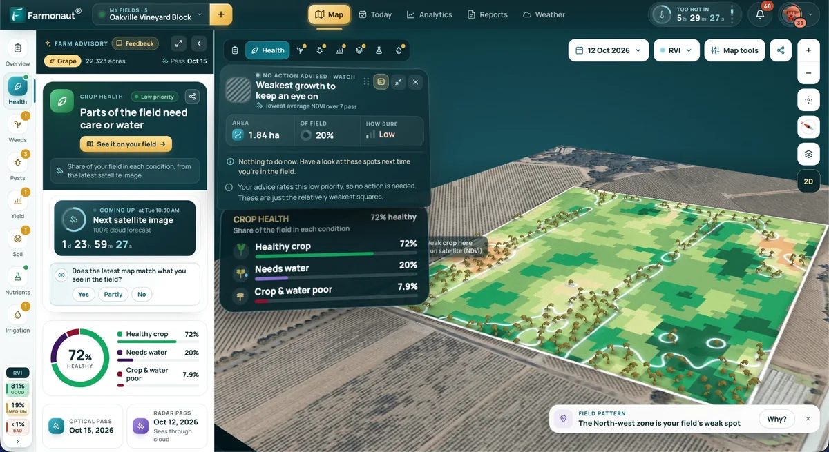
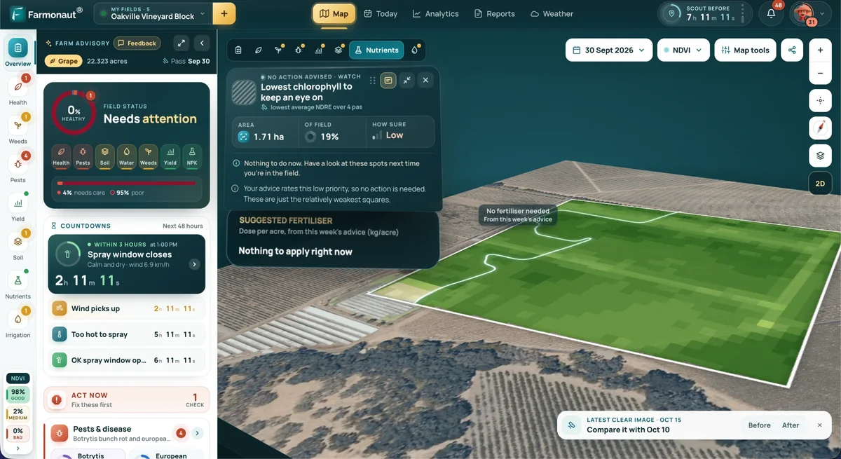
For mining operations managing tailings dam seepage risk across large or remote sites, Farmonaut's satellite-based mineral detection platform applies multispectral and hyperspectral satellite data to identify fractures, faults, and alteration zones that correlate with seepage conduits — before a field team sets foot on site.
- 🌐 Remote assessment: satellite data flags fractures and alteration zones linked to potential seepage pathways.
- 🤖 AI-driven analysis: accelerates identification of high-risk zones such as weathered rock or geochemically active layers.
- ⌛ Rapid reporting: georeferenced intelligence delivered in days rather than the months a ground survey campaign requires.
- 🌱 Reduced ground disturbance: fewer exploratory boreholes needed to characterize a site's seepage risk profile.
For deeper prospectivity analysis, vein structure visualization, and drill targeting in seepage-prone zones, Farmonaut's satellite-driven 3D mineral prospectivity mapping delivers actionable intelligence for exploration planning and downstream seepage risk reduction.
To integrate this geospatial intelligence into a mining operation's tailings dam risk program, request a quote via the mining query form, or reach the team directly through Contact Us.
Satellite-based structural mapping is a screening tool that narrows where ground-based seepage investigation should focus — it does not replace piezometers, seepage meters, or the on-site instrumentation program described above.
Frequently Asked Questions on Dam Seepage Control
What causes seepage in a dam?
Seepage is driven by the pressure difference between the reservoir and the lower-elevation area downstream, and it moves along whatever permeable pathway is available: cracks or joints in the dam body, fractured or permeable rock in the foundation, or the contact zone between the dam and the natural abutment.
How much water do you lose to dam and canal seepage?
USGS field measurements found 32% to 41% of inflow lost in unlined irrigation canals, and 20% to 50% lost in canals lined only with earth or native soil. Permanent lining cuts seepage losses by up to 97% compared to unlined sections, per USDA Economic Research Service data. A specific canal's actual loss should be measured with a USGS-style seepage run rather than assumed from these ranges.
What are the most effective dam seepage control methods?
The seven core methods are impervious cores and cutoff walls, zonal reinforcement with drainage galleries, downstream cutoff and toe drains, seepage relief wells and controlled outlets, grouting and grouted anchors, surface erosion protection, and continuous instrumentation with remote monitoring. Most working seepage control programs combine two or three of these rather than relying on one.
How much does dam seepage control cost?
Published case costs vary by an order of magnitude depending on scope: a plastic concrete cutoff wall at Back Creek Dam, Maryland cost $45 per square foot in 1990, while the Taylorsville Dam cutoff wall project in Ohio grew from a $2.6 million initial estimate to a $24 million final contract once full foundation conditions were known. Get a site-specific estimate rather than applying either figure directly, and check USDA-NRCS Cost Share data or state irrigation district reports for current material and labor pricing.
What percentage of dam failures are caused by seepage?
Historical USGS data on constructed dam failures attributes approximately 28% to piping and seepage-related mechanisms, making it one of the leading failure categories alongside overtopping.
Can satellite technology help assess dam seepage risk?
Yes — satellite-based spectral and structural analysis can map faults, fractures, and alteration zones that correlate with seepage pathways, narrowing where ground-based investigation should focus. It is a screening step that reduces the scope of field exploration; it does not replace on-site instrumentation such as piezometers and seepage meters.





Conclusion & Next Steps
Controlling seepage in a dam is a matter of matching the pathway — through the body, through the foundation, or along the abutment contact — to the correct one of the seven methods above, then instrumenting the result so a slow trend gets caught before it becomes an emergency. The measured cost of getting this wrong is not hypothetical: USGS puts piping and seepage behind roughly 28% of historical constructed-dam failures, and the Taylorsville Dam case shows a seepage remediation project growing from a $2.6 million estimate to a $24 million contract once full foundation conditions were known.
For mining operations managing tailings dam seepage risk, Farmonaut's satellite-based mineral detection and satellite-driven 3D mineral prospectivity mapping can narrow field investigation scope before committing capital to a full geotechnical program. Start by mapping a site at mining.farmonaut.com.
For a specific seepage control decision — canal lining, cutoff wall sizing, or an instrumentation plan — the durable approach that outlasts any single year's pricing is the same one used throughout this guide: characterize the site first, choose the method the pathway actually calls for, price it against current U.S. Bureau of Reclamation and USDA-NRCS references rather than historical case costs, and monitor continuously once it's built.
Discussion
Questions, corrections or field experience? Share them below. First-time comments are reviewed before they appear, and your email is never published.
No comments yet. Be the first to add a question or your experience.

 Tipareth Mines
 GemSprout Metals Limited
 Qader Group
 Ileys General Trading
 SG Gold Mining LLC
 VRV Global Pte Ltd
 Omsri International FZE
 G.I.T.T.
 Jaunita Erss Ltd
 Almosi SARL
 SRK Consulting
 Berks Gold Limited
 Mwerezi Minerals Company Limited
 Mining SARL
 SenGold Invest SAS
 Sean Mining Limited
 NTS Group (Pty) Ltd
 Mine4Africa